So ever wondered what the AIO of the new R9 Fury X looks like? Honestly – I didn’t. I just wanted to include the R9 Fury X into my own water cooling loop inside the EVGA Hadron Hydro. If you don’t know the case, have a look here and understand why you probably have to do it to fit everything in there.
So I’ve found a teardown of CPU AIO watercoolers. My idea was to get the impeller out of the pump, hook up some tubes and that’s about it.
And I thought – it’s from Cooler Master, so it won’t be much different – will it? Oh I was wrong, very wrong.
Update:
1. As pointed out by anddill some things were misinterpreted by me, I fixed that. Mainly: It’s not an IC under the flex PCB but the connector (obviously) and the black stuff is not for sealing the pump but for fixating the windings of the stator.
2. My card still lives, I killed my motherboard.
3. It seems like my custom tubes are leaking near the pump entry – I don’t know if I can fix that, but I’d strongly advice against doing it as I did.
As I took this pictures during my build, I didn’t spent a lot of time to get perfect pictures, sorry about that. And just as a word of warning: don’t do this, there is nothing to gain…
Let’s get started with something everyone should have seen by now:
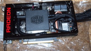
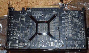
So you just remove 4 screws with a little hex key and you can see the internals in all their glory, not much to see here. To get further down, you remove all the cables, one for the RADEON illumination, one for the fan and one for the pump. Next you turn around the card and remove the backplate with a small phillips screwdriver (size 0 if I remember correctly). And you will see this:
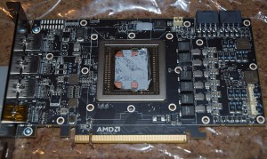
Alright, to get further down you have to remove the four screws of the spring holding the cooler on the die, all the screws on the back and also two screws on the bracket to release the frame of the cooler. Then you get to the mighty?, well surely enormous, die of the Fury. Looks like they tried fitting 8 stacks of HBM on there – at least there is some space left, but maybe that is needed for routing all the signals into the chip.
Taking the cooler further apart requires, I guess, criminal energy. They have used one way slotted screws to hold the cover on top of the pump and some nasty triangle shaped ones (I do not tamper with devices often these days, otherwise I would have had a correct bit for it I guess).
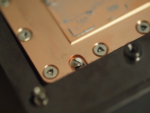
The security screws on the bottom plate of the R9 Fury X consist of four one way slotted screws and a few 1.5 mm triangle shaped ones
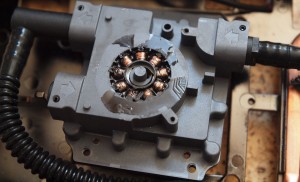
So the one way screws were no match for my laser-tipped Wera slot drivers, just apply enough pressure and they will come out again. So here is what’s below:
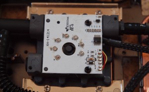
As you can see, they have soldered the PCB with the electronics directly onto the motor. The labels indicate a I²C communication to the main PCB and also some alert output for whatever purpose, what you don’t see yet is the flex electronics which goes down to the copper cooling plate – I suspect some sort of additional temperature sensor, and I have no idea why they would bother doing that – except maybe the temperature everyone is reading isn’t actually the core but only the copper plate, that would make the temperatures look much better than they are.
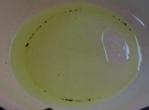
Next up is of course getting out those nasty triangle screws to see what the cooler looks from the inside. But wait, there is still water in the system. So first I have to get that out – trying to remove a tube without destroying it proved to be a fruitless effort, so I cut one near the radiator. A neon colored liquid came out of it – surely no simple water. Actually if you do some research, the R9 Fury X user guide from AMD suggests that it is some sort of „a mixture of monoethylene glycol / ethanediol“. Well I won’t drink it and you also shouldn’t get it on your hands either. A note maybe, the bowl I used is a very old one and the emaill has chipped off at some places, the liquid is (as it should be) clear and nice.
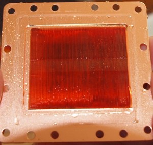
Okay now, ready to remove the triangle screws. As written, I don’t have a bit at hand for them, my brother thought that with a right sized hex key it should work, but none of them had the right size. So I used a Torx size 5 bit to remove four screws, then the bit broke. So for my next try I was lucky enough to have a true round bit from Hazet, it was marked as a PH2 bit, but is was really round, they forgot something during production I guess. What I did next was to use my trusty Proxxon mini multi tool and grind a triangle bit out of the round one. It worked reasonably well, if you turn the bit two hex sides between the steps you can get quite good triangles out of it. So with a self made 1.5mm triangle bit and a lot of pressure (yet again) I was able to remove all of the screws (I felt a bit proud). Out comes this:
It’s a rather simple design, very thin fins a small recess in the middle where the water is pressed in, around the fins a small groove is milled into the copper so the water can get to the exit.
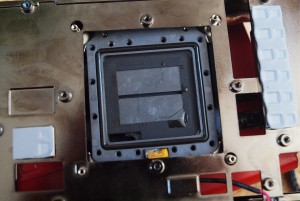
On the other side you get the pump block from the bottom side:
I’ve left in all the sealing rubbers. One is as expected a square one around the whole block. The other one covers the top of the fins, so that the water has to go through the fins and can’t take the easy way out. The slot in the middle is where the water is pressed in and the small rectangle at the bottom is where the water leaves the pump block. You can also see the flex PCB, which I suspect to be a temperature sensor.
I haven’t found any way to open up the block any further – I have no idea what they have done, maybe it is welded together. To complete the tear down I tried to get the PCB off of the top side. This turned out to be a bad idea (I think). After using a hot air gun and some force with the screw driver the PCB came off – in a bad way. Seems like the motor got so hot that in the end I pulled the contacts out of the motor and not out of the PCB.
So what’s there to see? Based on the research done by anddill over at the 3DCenter forum, the winding is loosely put into a hole which is then filled with some sort of glueish stuff to hold the winding in place. Failing to do so reliably which is also a cause for the noise and whining people are hearing from their pumps. Anyways I probably just have killed my pump.
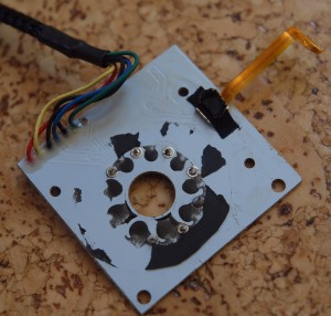
What’s the PCB looking like? Not much to see on the bottom:
You can see the pins I pulled from the motor, and the mounting of the flex PCB – there is also an IC under that black blob where the flex PCB is mounted.
Yeah and that is that. No way to remove the impeller from the pump, well I didn’t want to go to the extreme level and drill out the motor as I want to have it sealed. My suggestion for anyone trying to get the stock cooler integrated into a custom loop is to use the pump of the Fury as pump for the loop.
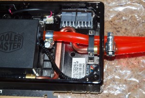
The good news is, that you can easily fit new tubes to the cooler:
Standard 8/10 mm tubes will fit just on the stock tube mounts, use some tube mounting things of which I don’t even remotely know how they are called in English and you are done. It is sealed tight and no water came out. Until I ran a burn in test with furmark and everything got hot, then it started to leak, so I advice against doing this – maybe I can get something better.
So big question: Does it still work? I don’t know, after finishing my build – which looked really nice, my machine wouldn’t start. It just shut itself off in 3 seconds. Now with everything removed my mainboard cycles on / off by itself every 3 seconds. Not sure if my Fury killed my mainboard because I killed the Fury or if I killed my mainboard during the installation of the water cooler. Surely I have killed something here. (*sadface*)
As a small update on this: I killed my mainboard, the card is working fine, even if you leave the pump electronics unconnected (good to know for other coolers like from EK).
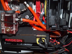
Now it’s looking like this:
Temps are horrible, especially my CPU is burning (literally @100°C), I’ve probably used too little pressure after killing my first board with too much pressure. And of course a custom build inside the Hadron is a bad idea as well (another story maybe).


I checked your website and I love it i want to try something similar with the fury. i just want to know what type of tube did you use for the GPU.
Hey Alejandro, I used a 10mm outer diameter and 8mm inner diameter tube. The tube was a highly flexible PVC type. I can’t recommend what I’ve done though. The temperatures I got were really really bad and as all the water heated up, there was a leak at one of the points where I connected the tube and wasn’t able to fix it.
After that I bought (for another 100 bucks) an Alphacool waterblock. With that the temperatures drastically improved and of course you get nice fittings and everything is nice and tidy.
I do miss my red RADEON light though…
Good luck, whatever you do with your fury 🙂
Hi! I want to do the same thing, but I have two Fury X cards and I also want to use my H100i AIO water block without its radiator. I am going to use 420mm and 280mm radiator. My goal is to achieve lower noise and 50C at max. My case is CM Master Maker PRO 5, so its spacious and have enough room for watercooling. What are your thoughts. Now I don’t have access to EK Copper Fury X block and thats my only alternative.
Hi Vladimir, not sure if I understand correctly – you want to leave the original cooler on and attach it to your custom cooling circle?
It will be very hard to get it really watertight as temperatures start to rise. I would keep the pump of the Fury attached so that it actually runs, because that way it’ll probably provide much less resistance and much better cooling. You radiators should be okay but I wouldn’t expect the quietest system under load with 2 Fury Xs and a CPU being cooled.
Hi! Thank you for the reply. Apreciate it alot. My project is going to be the following. I bought for dirt cheap a pump with reservior and use it in order to help the loop to have less resistance. I am going to use 8mm tubes starting from the pump, but I don’t really know if the Fury X pump have good flow rate(if you know tell me pls), but I can use a cpu block for 30$ Apogee one. I am going to use metal brackets like yours on the pic. with the Fury X and the res tubes. The metal brackets are going to be with screw and tighten the connection. With two Fury X I should have good flow until the CPU H100i’s pump that will make presure in the 12mm tubes from the radiators and end up in the reservior. Why your system had worst resoults. Was that due to not enough radiator/s size. For fans I am going to use Noctua 3000RPM Industrial PPC.
I’m not sure about the flow of the Fury X pumps, but the effect of flow has been tested on several websites and hardware magazines. The result was that the flow has an negligible effect on the cooling performance. My system performed very badly because I damaged the pump and it was standing still, so it probably stopped the flow almost completely.
Maybe you could use some silicone to seal the area around the metal brackets better. That is where I had the biggest problem (I had two leaks, very lucky nothing got damaged, the PSU is under my GPU and it got quite wet). And yes, my radiator size was also probably too small for my system (4790K + Fury X running on a small 240 mm radiator in the first go). Later on I added an external 200×200 mm radiator and then it was fine, but at that point I already exchanged the original cooler for one from Alphacool.
So I think you will be fine as long as you get the adaption on the Fury X watertight.
Hi, Arsenal! I did the loop with the Fury X stock pumps and found that it isn’t so bad. Actualy it worked better than I thought. In your review you said that 8/10 tubes are enough, but the Fury X’s hoses required 6mm(I have used 6/10 tubes that are made from Vitryll and stand up to 240C. For clamps I used that with a screw and it perfectly fitted. The loop is running in parallel, but if your pp is whiny it will move water faster. It comes from my testing that the noisiest GPU is actually cooler. The 1st GPU is staying at 40 and the 2nd is 42. I didn’t have any leaks, due to the correct size of tubes. The system is the following: The pump sends water from the reservior to the GPUs. The GPUs are connected with 1 T-connection and one 90° ankle and forms a F-connection for input and output. Then a 6mm tube is entering the CPU and the second CPU port is starting with 8mm. Then another pump is sucking with 350L/h and sends the water to a 420mm radiator that’s 45mm thick. The second pump actually lowered my temps, becouse without it, the GPU temp was like 44(1st GPU) and 50C(2nd GPU). The CPU(7700k at 5.1Ghz) was 65C for the record. BTW it’s delidded. For fans now I use 3xCooler Master stock case fans(140mm) up to 1200RPM with 3-pin connector that pull the air and another 3 Noctua 120mm 3000RPM industrial PPC at 1300RPM for the sake of silence that push the air. At the end I found 2 EK-FC Fury X water blocks with backplates for 30$ in ideal condition like new and bought them in order to replace the stock water blocks. For those like me in the begining that want for cheap to make a custom loop: Don’t worry for doing such a strange build, just be careful and check the flow. I did that, becouse I wanted to see what will happen when I add everything in one system with one big radiator and how the thermals will end up. I ended up with 3 different configurations of the setup, but finaly acheved this. My thoughts: I will let that system to flow with ease, untill I buy full-cover water blocks and it happened like I had thought. If you are scared, there’s nothing scary. The stock water block does fine and works in reality like a full-cover water block, just keep in mind that the pump may die and end up with dead card. The idea behind that project was about performance compared to my friend’s Fury X water block. Afterwards, they are the same performers, but the stock may make a noise for your ears and limits the flow at point, but enough for proper flow.
Hi Vladimir, thanks for the feedback and the useful information. Seems like my main issue was then, that my pump was just way to underpowered to overcome the resistance of the original block. Good to know that the 6 mm tubes are the correct size to get it tight.
Wow, man, it’s no wonder you got those temps, loop without pump is like an air cooler without a fan (maybe even worse) it has some heat capacity, but doesn’t have dissipation at all.
I had the pump of my custom loop attached to it. It wasn’t powerful enough as it seems (based on the comment by Vladimir, it’s doable).
„I had the pump of my custom loop attached to it. It wasn’t powerful enough as it seems (based on the comment by Vladimir, it’s doable).“
Oh, sorry, my bad, must have missed part about extra pump in original post.
I have a similar idea, described my plan in this reddit post:
https://www.reddit.com/r/watercooling/comments/d1rtf0/diy_broken_pump_in_corsair_h100i_aio_reuse_cpu/
Did you attempt to do the build? What are your impressions?
Sorry, I delayed the comment by Vladimir, be sure to read his new comment.
„The pump sends water from the reservior to the GPUs.“
So, just to be clear: you never had a setup, where only pumps in the loop would be the ones in Fury X blocks? I want to make use of Corsair AIO with broken CPU block pump and replace Fury X radiator with Corsair radiator and CPU block so Fury X block pump would be only pump in system and Corsair 280mm radiator would be only rad in CPU + GPU loop.
(in this reddit post I described my plan https://www.reddit.com/r/watercooling/comments/d1rtf0/diy_broken_pump_in_corsair_h100i_aio_reuse_cpu/ )
The thing I am worried about is if Fury X block pump is strong enough to push liquid through two blocks and one bigger radiator. Wat do you thing about rest of my concerns I described on reddit?
Hi, Arsenal! I did an upgrade on my current loop with two EK FC water blocks. With the same fan speed on my 6 fans(3xNoctua Industrial PPC 3000RPM 120mm and 3xCM 140mm Case fans) I stuck at 47C. The GPUs are in parallel(like the last time with the stock water block) and the flow is almost 1GPM. The tubing is still 8mm and limits the pumps(the pumps are the same 1xDDC 4.7m 600L/h and 1x350L/h 2.5m) so I decided to upgrade the tubing too to 10mm, becouse tests proved that. from 10 to 13mm the change is like half or 1C, which is within margin of error. I want to post pictures from my prevous configuration with the stock blocks and provide data and my thoughts and my new configuration with the EK blocks. I also got them for like 35$ in condition very close to new(that’s the reason for the upgrade) and after I fully test the system, I am going to send the data.
May we make a new thread about the Fury X project and provide enough data to support the puctures. There’s a lot to talk about. If people see that, they would be more confident for a new project like that, including tear down water coolers and use them as water block. It seems like people are trying to make that and search for information. The DIY thread with stock water coolers would be searched a lot. Send me discord or something via e-mail to my e-mail if you are interested in.
Hey Bernhard,
it would be nice if you could let me know which exact screwdriver you have used on those one way screws? I have bought a cheap tr4 360mm kit and need to remove the copper base plate of the pump, in order to get access to the screws for the socket specific clamps. My attemts with a normal flat head screwdriver failed so far. Are the laser cut groves in the wera screwdrivers helping a lot?
Viele Grüße aus dem Schwabenländle,
Benjamin